Facilities
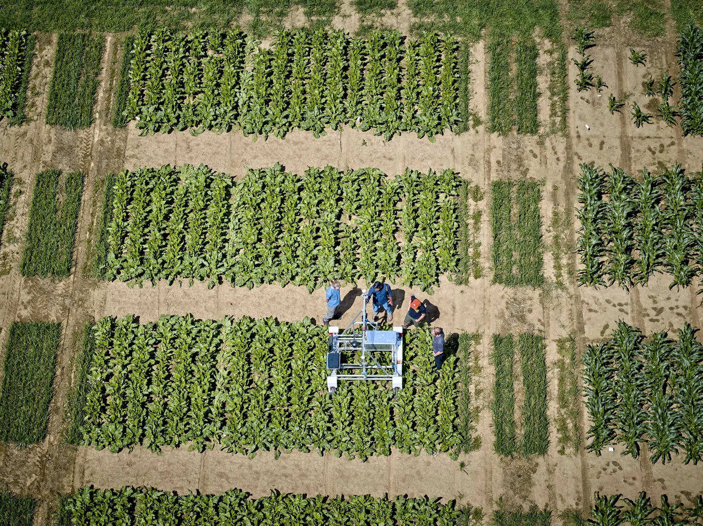
Agricultural Research Campus Klein-Altendorf
The Research Campus Klein-Altendorf covers approximately 10 hectares and serves as a key site for developing and testing agricultural robots and sensors under realistic field conditions. The data collected from plant growth and traits here supports modeling and digital agronomy efforts within the Cluster of Excellence PhenoRob. It also contains the PhenoRob Central Experiment, which is alarge scale real-world testbed for agricultural robots, drones and ground truth data for phenotyping.
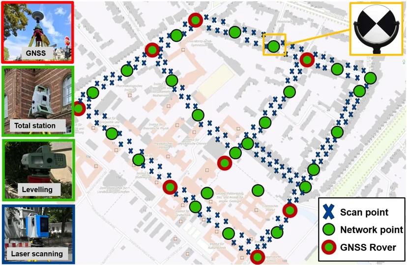
Evaluation Environment For Mobile Laser Scanning Systems (MoLaB)
In the urban environment around our institute we created a test environment to empirically evaluate the geometric accuracy of 3D maps captured with mobile sensing systems. We use multiple features from the test site to analyze the accuracy of different parameters, which can be extracted from the captured point cloud. The test site is accessible by any mobile mapping system to drive through and collect data. A set of quality parameters can be automatically derived from the georeferenced point clouds provided by the system.
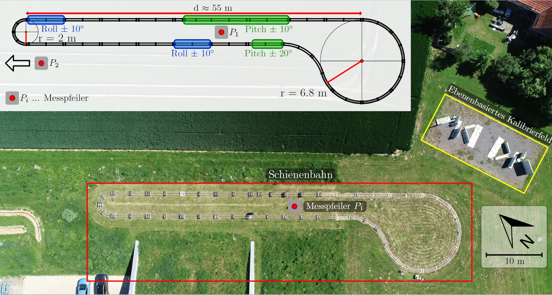
Rail-based Test Environment for Mobile Mapping Systems
It is about 140 m long and has variations in all six degrees of freedom, i.e. position and orientation. Several precisely positioned pillars are located in the vicinity of the rail track . They can be used to georeference target-tracking sensors such as total stations with sub-mm accuracy. With the help of a motorized rail car, a rail wagon mounting navigation sensors can be moved automatically along the rail track. This enables repeated kinematic measurements in several laps. The maximum speed of the rail car is 0.8 m/s

Calibration Field for Mobile Mapping Systems
We developed a calibration field and a procedure for mobile laser scanning system calibration, which is based on the following steps: An area with multiple concrete planes has been created, optimized for calibration purposes. The plane parameters have been determined using a terrestrial laser scanner. A point cloud of the calibration field is created with the system under calibration, using initial calibration values. By comparison of the resulting points with the reference planes the calibration parameters are estimated accurately using a least square approach